
 Timing belts
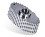 Pulleys
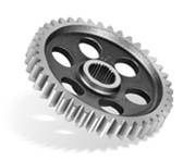 Gears
Gears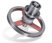 Assembly units
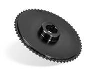 Sprockets
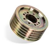 V-belt pulleys
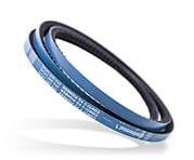 V-belts
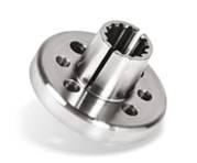 Metal cutting
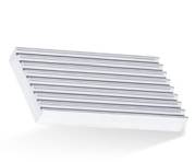 Machine parts
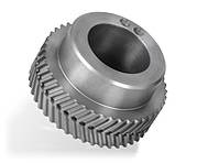 SilentSync Tooth Lock Washers
 Sawing
 Turning
 Milling
 Gearing
 Eroding
 Grinding
 Gear grinding
 Mounting
 Heat treatment
 Surface treatment
 Quality assurance
 Logistics
Gearing
At WIAG Antriebstechnik we have a variety of manufacturing processes for the production of toothed gearing systems. These processes are duly selected so as to be in perfect accordance with the component in question and its future application.
For the manufacturing of external toothed systems for gears and pulleys, it is usually the classic hobbing process which is used. This process involves the part turning around a vertical axis with the motion of the cutting tool and workpiece generating the required helix or angle of incline. The feed motion is carried out in the direction of the vertical axis. All such work is performed on 12 ultra modern CNC milling machines designed for gear cutting and manufactured by Liebherr, Köpfer and Gleason Pfauter.The machines can be operated either manually or automatically and are equipped with state-of-the-art air and oil filter systems. Such machinery enables diameter sizes ranging from 10 mm up to 800 mm to be turned out.
![[Translate to English:] Prozess Verzahnen](/fileadmin/user_upload/prozesse/verzahnen/WIAG1176.jpg "[Translate to English:] Prozess Verzahnen")
![[Translate to English:] Prozess Verzahnen](/fileadmin/user_upload/prozesse/verzahnen/WIAG1219.jpg "[Translate to English:] Prozess Verzahnen")
![[Translate to English:] Prozess Verzahnen](/fileadmin/user_upload/prozesse/verzahnen/WIAG1251.jpg "[Translate to English:] Prozess Verzahnen")
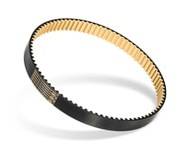
All timing belt gears (profiles and pitches) and also spur gear tooth systems from module 0.8 up to module 8 can be produced. Hard machining such as skive hobbing and also bespoke, position-related gear cutting are all part of our standard procedures.
During the skive hobbing process of tooth systems, hardened gears are remilled in order to enhance the quality of the toothing. As is the case with tooth flank grinding, this procedure entails the removing of only a slight size discrepancy by machining so as to eliminate any possible hardening distortion. But in contrast to tooth flank grinding, this procedure has the advantage that at the moment it is more reasonably priced and it also does not create any grinding burn.
![[Translate to English:] Prozess Verzahnen](/fileadmin/user_upload/prozesse/verzahnen/WIAG1224.jpg "[Translate to English:] Prozess Verzahnen")
![[Translate to English:] Prozess Verzahnen](/fileadmin/user_upload/prozesse/verzahnen/WIAG1247.jpg "[Translate to English:] Prozess Verzahnen")
![[Translate to English:] Prozess Verzahnen](/fileadmin/user_upload/prozesse/verzahnen/WIAG1263.jpg "[Translate to English:] Prozess Verzahnen")
With position-related gear cutting, the generated toothed profiles can be very precisely aligned with specific contours or bores, which are manufactured in advance. Such work frequently allows the production process to be significantly more cost-effective.
![[Translate to English:] patentierte elliptische Verzahnungen](/fileadmin/user_upload/prozesse/verzahnen/W058.jpg "[Translate to English:] patentierte elliptische Verzahnungen")
The patented elliptical gear cutting of pulleys is performed in a single-cycle process. For this procedure, the contour coordinates are firstly calculated by specifically developed software. This information is then read and every tooth subsequently individually milled.
We have two manufacturing options available for the cutting of internal toothed systems. On the one hand, there is the broaching method with the appropriate tools known as broaches. One example of when this is implemented is plug shaft toothed systems DIN 5482 or also other systems with a broaching force of up to 14,000 KG. Here we are normally dealing with internal toothing with a maximum diameter of 60-70 mm and with through holes. On the other hand, there is hob peeling or power skiving. Hob peeling is carried out on a turning-milling centre. This procedure lends itself just as well to internal as to external tooth profiles. And it requires considerably fewer run-outs and overruns than is the case with hobbing. The process of hob peeling is used with toothed systems that are suitable for hobbing and broaching. It can also be implemented with some components associated with gear shaping.
The tool used is a "gear" with cutters on the front. As a result of the crossed axis arrangement of the tool and the workpiece, an axial relative speed is generated, which brings about the cutting movement. The crossing of the axes causes the helix angle of the tool and the helix angle of the gear that is being produced to differ from each other by the angle of the coordinate axes.
Next to this inclination for the angle of the coordinate axes, there exists a tilt angle, the inclination of which is vertical to the rotational axis of the tool and also vertical to the inclination in respect of the angle of coordinate axes. This tilt allows a clearance angle to be achieved between the tooth flanks of the tool and the tooth flanks of the workpiece.
Furthermore, two linear shifts are necessary. The reasons for this is that, firstly, the distance between the workpiece axis and the tool axis has to be set and, secondly, the tool has to be moved along the workpiece axis. This shifting of the tool along the workpiece axis requires a rotation that is to overlap rotation of the tool and the workpiece, depending on the angle of the coordinate axes. This is called differential speed.
Compendium of profiles and pitches - timing belt toothed systems
| [Translate to English:] Profile | Pitch |
|---|---|
| HTD | 3M |
| HTD | 5M |
| HTD | 8M |
| HTD | 14M |
| HTD | 20M |
| Powergrip® GT | 3M |
| Powergrip® GT | 5M |
| Powergrip® GT | 8M |
| Powergrip® GT | 14M |
| Powergrip® GT | 20M |
| STD | 2M |
| STD | 3M |
| STD | 4.5M |
| STD | 5M |
| STD | 8M |
| STD | 14M |
| SilentSync® | 8M |
| SilentSync® | 10M |
| SilentSync® | 14M |
| T | 2,5 |
| T | 5 |
| T | 10 |
| T | 20 |
| AT | 3 |
| AT | 5 |
| AT | 10 |
| AT | 20 |
| ATP | 10 |
| MXL | 2,032 |
| XL | 5,08 |
| L | 9,525 |
| H | 12,7 |
| XH | 22,225 |
| XXH | 31,75 |
| Polychain/Synchrochain® | 8M |
| Polychain/Synchrochain® | 14M |
| Powergrip® GT3 | 2MGT |
| Powergrip® GT3 | 3MGT |
| Powergrip® GT3 | 5MGT |
| Powergrip® GT3 | 8MGT |
| RPP® | 3M |
| RPP® | 5M |
| RPP® | 8M |
| RPP® | 14M |